
Welcome to The Inexpensive Seismometer Project! See
 for latest page updates.
These pages describe my project to build simpler and less expensive amateur seismometers by using microprocessors and other new chips, such as switched capacitor filters. I have tried to provide links to much of the excellent information that is already on the web. And I have tried to fill in some of the gaps in the existing information. For instance:
PROJECT STATUS: I have completed an improved design of my PCB, incorporated
a lower noise amplifier (ADA4528-1 surface-mount zero-drift amplifier),
and added a diecast alumimum enclosure for thermal and
electromagnetic shielding. This improved my system noise floor by about 5x. Systems
and kits based on these improvements are now for sale.
Specifications and ordering information for QM-1.0 long-period one-axis seismic electronics for long period sensors (including the Lehman design)
Specifications and ordering information for QM-4.5 short-period one-axis seismic system that includes a geophone sensor.
QM-4.5-ADXL103 one-axis strong-motion accelerometer. My simplified electronics design uses only 4 chips for the amplifier, 8 pole Bessel filter, 16 bit a/d, and serial output. These boards are powered by the PC serial port, and they are designed to work with the freeware data log/display program Amaseis. Please , if you are interested.
USGS: BIGQUAKE, QEDPOST, MTALL sign up to receive email alerts about earthquakes.
Guidelines for Installing Broadband Seismic Instrumentation
expert guidance, not necessarily for amateurs, but it may give
you some ideas.
Hubbard Scientific Seismograph Model (Earthquake Sensing Kit) Grades: 6 - 12.
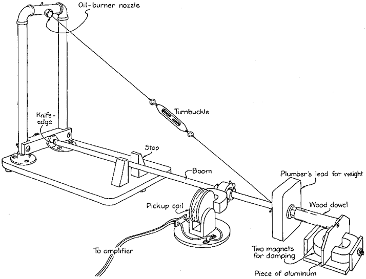
What are the basic components of a seismograph?
BASIC COMPONENTS
I will start with electronics since I think that is where most folks who want to build their own system bog down.
Most of the seismic circuit designs that I have seen do not use microprocessors and they use filter designs that require lots of precision components. They generally have one amplifier/filter board and another board with A/D and PC interface. They also use dual power supplies.
I have attempted to make use of some of the recent advances in low-power, precision chips and mixed signal microprocessors. My design goal was a single board that did everything with a minimum number of inexpensive components, and could be run off a single 9 volt battery for 100 hours (or no power supply at all!).
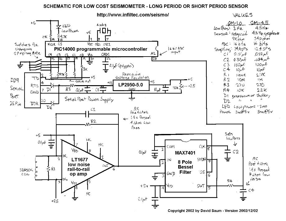
Here is my simplified design for Lehman, geophone, and accelerometer electronics. It requires a single-ended 5.1v to 16v supply and generates serial (RS-232) data output. There is no sacrifice in signal processing quality due to the 8-pole Bessel filter and 16 bit a/d. My circuit uses only 4 low-power chips:
For low impedance sensors like geophones I like the LT1677CN8 Low Noise, Rail-to-Rail Precision Op Amp. It works best with a source resistance (Rs) less than 400 ohms and possibly up to Rs as high as 8k ohms. Above that Rs, the data sheet says the noise is significantly higher. However, this chip seems to work well with my 9k Lehman coil. The chip requires 5 volts, single supply, 2.85 ma. Specs include noise ~70 nV/\/Hz\ @10 Hz, CMRR ~109 dB, Offset Drift ~0.2 uV/C, Input Offset Voltage ~60 uV.
For higher impedance sensors I like the TLC2201CP Low Noise Precision Rail-To-Rail Output Op Amp. The TLC2201ACP and TLC2201BCP have better guaranteed specs. This chip requires 5 volts, single supply, 1.5 ma. Specs include noise ~30 nV/\/Hz\ @10 Hz, CMRR ~85 dB, Offset Drift ~0.5 uV/C, Input Offset Voltage ~500 uV.
Since the op amp output goes into the switched capacitor filter it is necessary to suppress any high frequencies that might be mixed by the switching frequency. I find that an RC filter using a capacitor (Cf) across the op amp feedback resistor (Rf) works fine if I set the RC filter cutoff (Fc1) to about 1.5 times the switched capacitor cutoff (Fc2). For instance, if the Fc2 is 1 Hz for a typical Lehman, then Fc1 should be 1.5 Hz, and Cf should be chosen so that Fc1= 1.5 Hz = 1/(2*Pi*Cf*Rf). For 4.5 Hz geophones, I set Fc1 to 4.5 Hz and Fc2 to about 6.8 Hz. For ADXL105 accelerometers I use the same filtering as I use for the 4.5 Hz geophones, and I use the on-board op amp rather than a separate gain op amp.
SAMPLING RATE - The 4 MHz PIC14000 can perform 16 bit A/D at about 60 samples per second (SPS) and these samples can be averaged in software for noise rejection. I have written the firmware to allow for a dip switch selection of averaging times from 4 SPS to 20 SPS.
SERIAL DATA FORMAT - Each output sample is an ASCII record terminated by LF and CR. The samples range from -32767 to +32767. This format can be read by the AmaSeis seismic data acquisition program. Output from Amaseis can be further analyzed by the WinQuake seismic event viewing software.
PICTURES AND DIAGRAMS OF MY LATEST SYSTEM DESIGNS
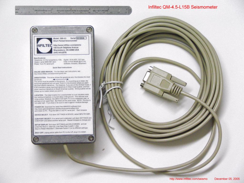 Infiltec QM-4.5-L15B exterior.
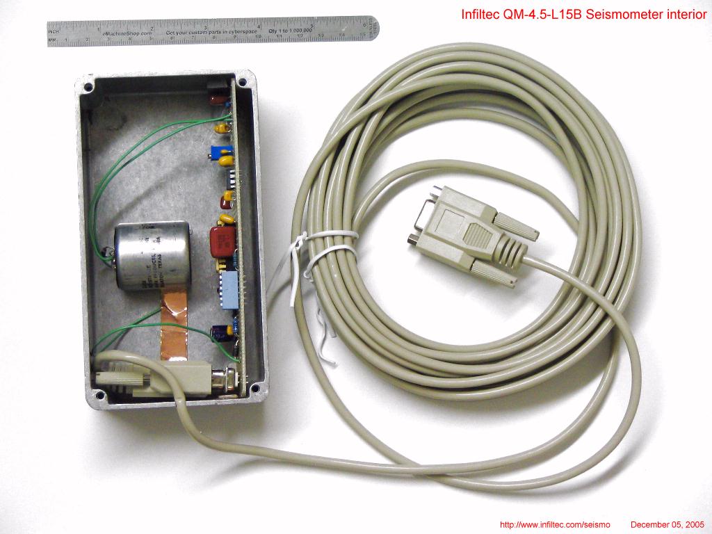 Infiltec QM-4.5-L15B interior.
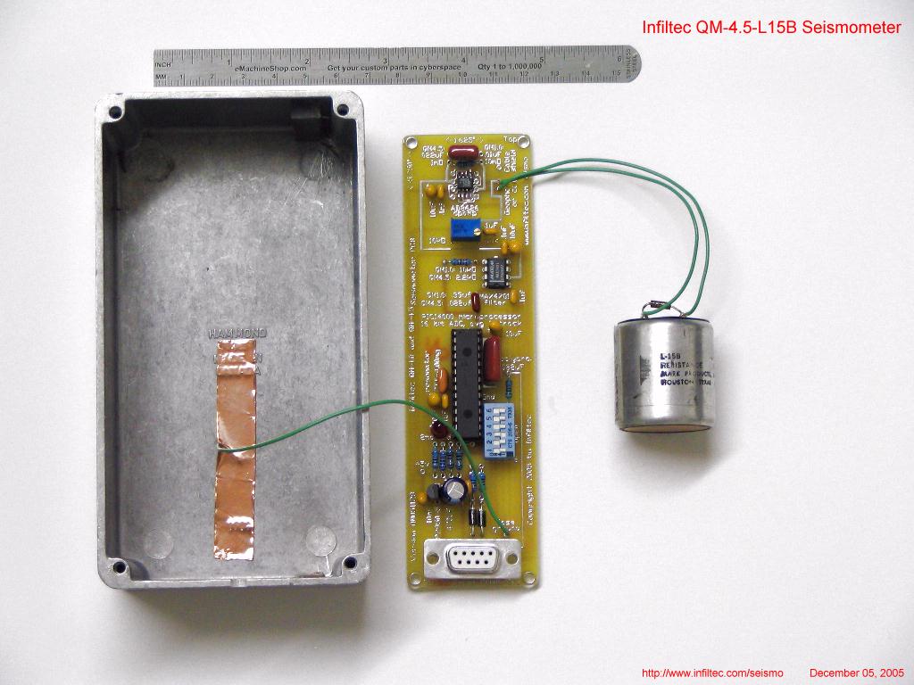 Infiltec QM-4.5-L15B circuit board, enclosure and
4.5 Hz geophone.
Infiltec QM-4.5-L15B circuit board, enclosure and
4.5 Hz geophone.
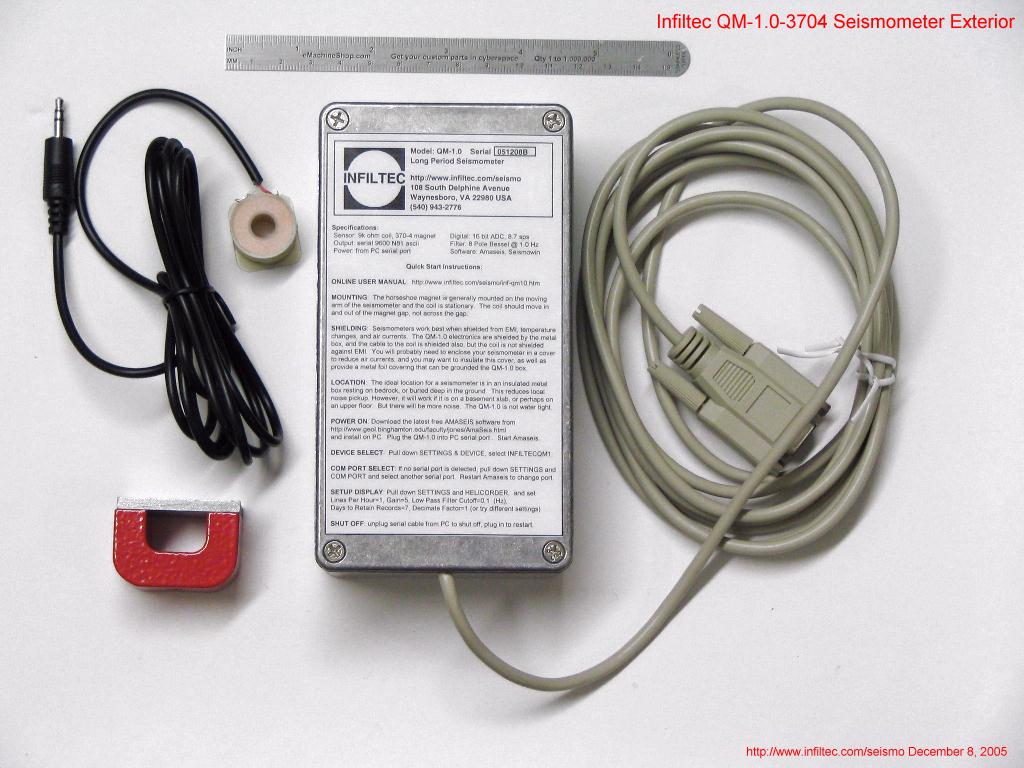 Infiltec QM-1.0-3074 Exterior.
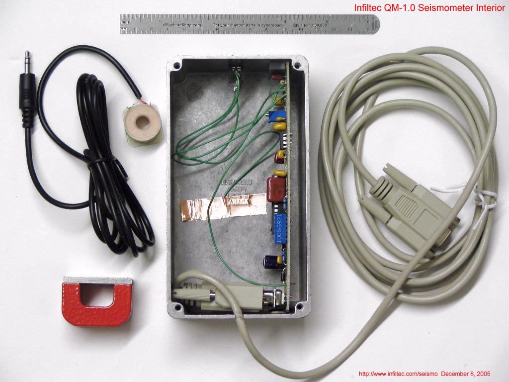 Infiltec QM-1.0-3074 Interior.
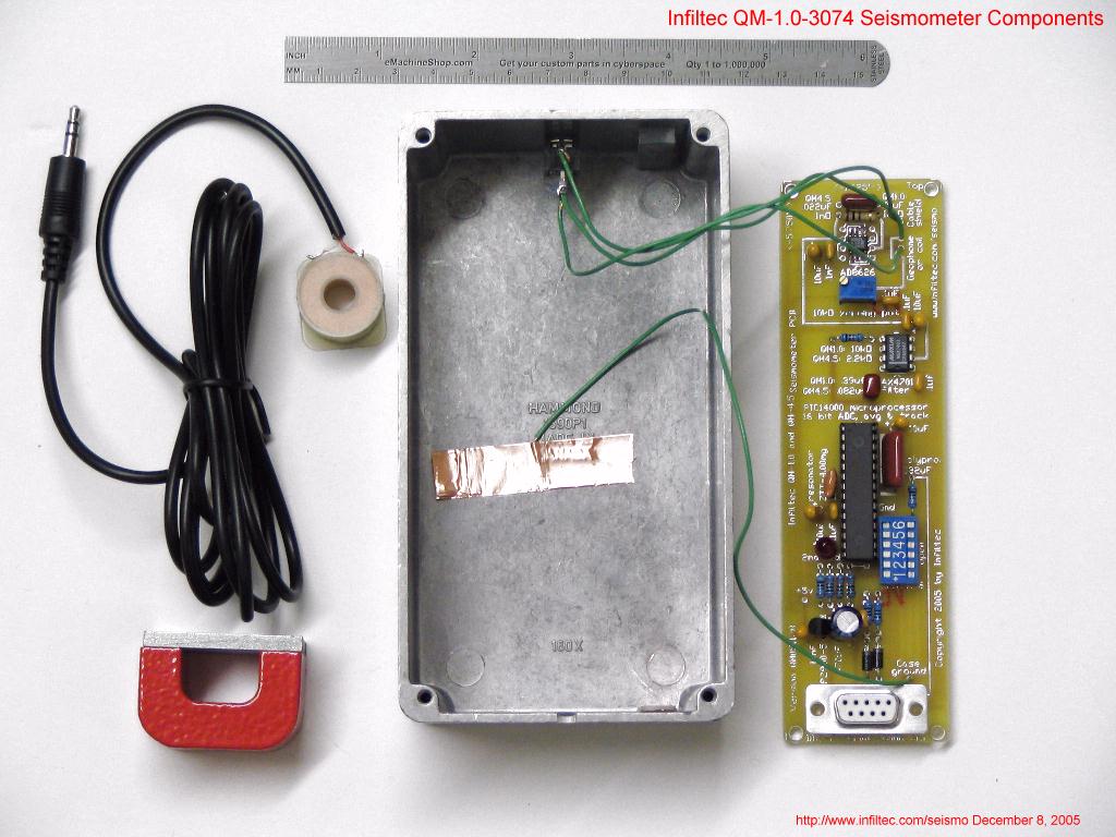 Infiltec QM-1.0-3074 circuit board, enclosure,
pickup coil and magnet.
Infiltec QM-1.0-3074 circuit board, enclosure,
pickup coil and magnet.
Note that the long period QM-1.0 seismometer printed circuit board is identical to the QM-4.5
board except for passive component value changes to reduce the low pass filtering to 1 Hz.
The QM-1.0 is designed to work with a 9k ohm pickup coil and moving magnet.
Here is the QM circuit schematic diagram.
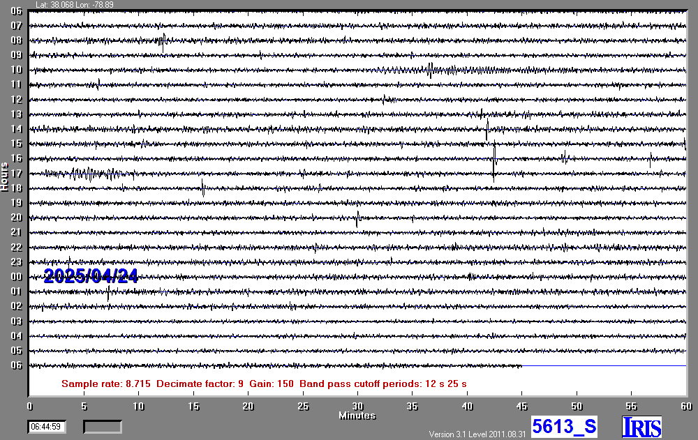
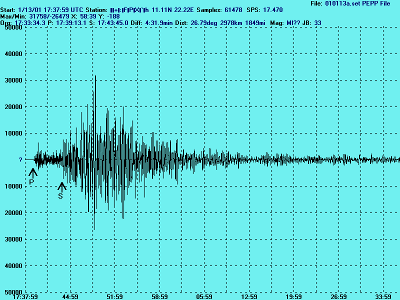
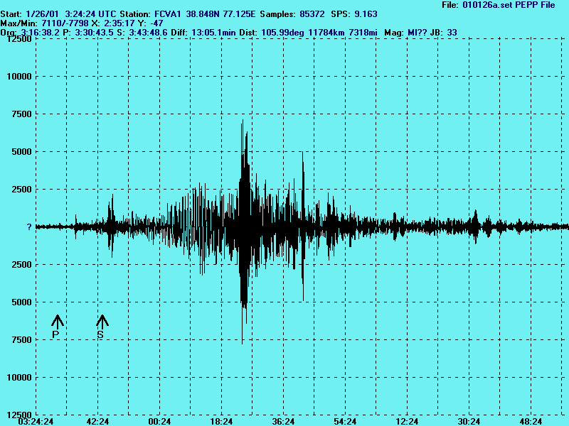
SAMPLE OUTPUT - How well does this circuit work? Here is the January 13, 2001 magnitude 7.6 Central American quake, detected with my QM-1.0 Lehman from approximately 3,000 km away, that almost saturates the electronics (+/-32767). And here is
Here is a pretty good design that I found on the web by Andy Loomis. -->
How much is it going to cost you to build a Lehman long-period seismograph? It depends on how much you want to build and how much you want to buy.
In order to use most seismic software you will have to know your site latitude and longitude. There are many web sites that can compute this from your street address. I used Eagle Geocode to compute mine. BTW, once you know your location you can watch for satellite phenomena like Iridium Flares.
In order to point your seismograph you need to use a compass. Most of us folks on the East Coast of the US align our seismographs E-W in order to be most sensitive to California and Asian quakes. By "align" I mean that the swing direction of the pendulum is pointed that way. Of course you may want to correct for the fact that your compass does not point to "true North" because of magnetic declination. For instance, I am in Northern Virginia where the declination correction is -9 degrees. So true North for me is actually 9 degrees off compass North. To correct for declination you must rotate your compass counterclockwise to correct on the East Coast and clockwise on the West Coast (where the declination correction is positive.) This is not a big correction for me, but it could be over 20 degrees if you are in the extreme NW or NE US. Even that does not make a big difference with seismometer sensitivity since the low frequency teleseismic quakes are not highly directional. Here is more information on finding True North from the sun's position.
My system sits on the basement slab of a VA office building about 100 feet from an continuously operating HVAC unit, with a major road about 100 ft on one side, and a McDonalds drive through about 50 ft away on the other. During the day the record shows many spikes similar to what happens when someone walks near the pendulum and deforms the slab. I get some pretty quiet data in the middle of the night when the Big Macs go home.
You will need to get an accurate time reference to Coordinated Universal Time (UTC) (Greenwich England time without daylight saving time) since you want to know the arrival time of quakes within a second of UTC. Some folks hook their electronics to GPS or WWV radio systems but I have not tried that. I looked for some way to make my PC clock accurate to within a fraction of a second per week instead of its usual several seconds per hour of error. Here is what I came up with:
I found when I started my project in 2000 that most of the existing seismic data logging software was programmed to accept data from a few PC a/d boards, and most of the programs did not accept the ASCII data records that microprocessors can easily output. However I found one program that the author was willing to modify to accept simple ASCII records: the freeware program Amaseis. Here is all of the seismic software that I am have heard of that might be of interest to amateur seismologists. Please send me links to all the software I have missed.
jAmaSeis
IRIS seismic data logging software for Windows, Mac, Linux (free).
NetTime download, or
NIST Internet Time Service download
Windows time synchronization (Free).
SAC_to_PSN
Conversion of AmaSeis SAC files to speeded up WAV audio files for Windows (free).
Raven Lite
Conversion of Audio files to Waterfall display for Windows (free)
Go to the windows "control panel" find "power options" and then "edit options" and where it says "when plugged in"/"put computer to sleep" change that option to "never".
Another way to make this change is to click on the windows start button, and type "power options" where it says "search programs and files" then it should show "power options" under "settings" and when you click on this, it will take you to the "edit plan settings" screen where you can select "never" sleep as your option.
Note that another way that AmaSeis may stop recording occasionally is if you reduce the AmaSeis 24hour data display screen to the task bar. That seems to reduce the priority of the program so that the serial data input does not keep up and crashes AmaSeis (hours or days). Always keep the AmaSeis screen full screen, even if it is covered by another program's screen.
Another way to reduce the AmaSeis processing load on your pc is to set the DECIMATE factor to about 9. At the start of each hour the 24hour display is redrawn and that redraw can increase the load on the cpu, but a decimate factor of 9 will only redraw every 9th data point, which speeds up the redraw without much change in the readability of the display. This may eliminate any unexplained AmaSeis dropouts that occur on the hour change.
Most USB-serial adapters will not work because they can not supply the voltage and current necessary. The USB ports on all computers can supply the necessary power, but the problem is when the 5vdc from the USB port is converted to ~9vdc on some of the serial pins. Most adapters fudge on this. So the serial communications will generally work fine, but the unit will not have enough power to work reliably.
To measure PPV you must select an time segment on the 24 hour display to analyze, then block the segment with your right mouse cursor, and then press the "~" shaped button at the top left of the AmaSeis screen. This will display the number of counts in the vertical axis, and you can chose a peak to analyze. Note that you can not make the PPV measurement on the frequency spectrum display.
Each count represents the following value of PPV, depending on which seismometer you have:
QM-4.5LV PPV @ 1 Hz vertical: 3.5*10^-6 mm/s/count or 0.13*10^-6 inch/s/count
QM-4.5V-20HZ PPV @ 4.5-20 Hz vertical: 4.9*10^-6 mm/s/count or 0.19*10^-6 inch/s/count
For example, if you have a QM-4.5LV, then a spike of 10000 counts on the amplitude display represents a Peak Particle Velocity @ 1 Hz vertical of .035 mm/s or .0019 inch/s.
Mesmsic thermal based accelerometer chip (comparable to Analog Devices)
Parallax accelerometer sensor uses Memsic digital output chip.
Brown Dog Component Adaptors DIP adaptors for surface mount chips.
Digikey: Surfboard
adaptors to go from surface mount to through-hole (pdf file of
catalog page).
PCE Instruments
Measurement Instruments Supplier.
Industrial Instrument Needs
Measurement Instruments Supplier.
PCE Instruments
Measurement Instruments Supplier.
Industrial Instrument Needs Measurement Instruments Supplier.
AktivFilter software for designing perfect active filters with real components.
Geophone Model L-28 spec sheet (224k pdf).
Geophone Model L-15 spec sheet (205k pdf).
My
Infrasound@home how to build an inexpensive microbarograph for detecting infrasound(sounds below 20 Hz).
![]()
This page copyright © 2001-2016 by Infiltec Inc., all rights reserved. Last updated on September 09, 2016.